VR Builder Manual
Table of Contents
- VR Builder Manual
Introduction
VR Builder helps you create interactive VR applications better and faster. By setting up a Unity scene for VR Builder, you will pair it with a VR Builder process. Through the VR Builder process, you can define a sequence of actions the user can take in the scene and the resulting consequences.
You can easily edit a process without coding through VR Builder's process editor. The process editor is a node editor where the user can arrange and connect the steps of the process. Each step is a different node and can include any number of behaviors, which make things happen in the scene. Likewise, a step will have at least one transition leading to another step. Every transition can list several conditions which have to be completed for the transition to trigger. For example, step B can be reached only after the user has grabbed the object specified in step A.
Behaviors and conditions are the "building blocks" of VR Builder. Several of them are provided in the free version already. Additional behaviors and conditions are available in our paid add-ons. Since VR Builder is open source, you can always write your own behaviors and conditions as well.
Behaviors and conditions can interact only with process scene objects. These are game objects in the scene which have a Process Scene Object component on them.
The interaction capabilities of a process scene object can be increased by adding scene object properties to it. For example, adding a Grabbable Property component to a game object will let VR Builder know that the object is grabbable, and when it is grabbed.
Normally it is not necessary to add properties manually to an object. When an object is dragged in the inspector of a condition or behavior, the user has the option to automatically configure it with a single click.
Where possible, properties try to add and configure required components by themselves. If you add a Grabbable Property to a game object, this will automatically be made grabbable in VR (it still needs to have a collider and a mesh, of course).
This makes it very easy to start from some generic assets and build a fully interactive scene.
Requirements
VR Builder is supported on Unity 2021.3 or later. It uses the built-in render pipeline by default, but URP is supported as well and existing materials can be easily converted.
VR Builder works out of the box with any headset compatible with Unity's XR Interaction Toolkit.
Installation
You can get VR Builder from the Unity Asset Store or from our GitHub. In the first case, you will be able to download and import the VR Builder package from the package manager. If you have downloaded a .unitypackage from GitHub, just import it in the project.
If you are creating a new project, select the 3D or 3D (URP) template. Note that it is not necessary to choose the VR template as VR Builder will configure the project for VR automatically.
After importing, VR Builder will compile and import some dependencies.
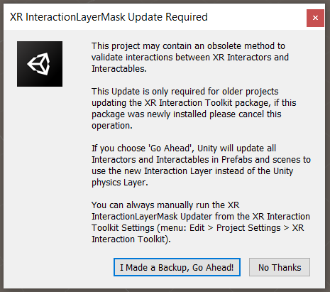
For older Unity versions, a dialog from Unity's XR Interaction Component appears. VR Builder should work with either choice, so select the option that better suits your existing project. Use I Made a Backup, Go Ahead! if you are starting a new project. This will trigger an automated restart.
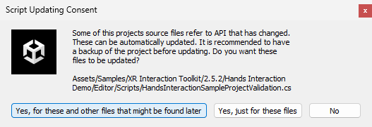
For newer Unity versions the Samples of the XR Interaction Toolkit might need an update.
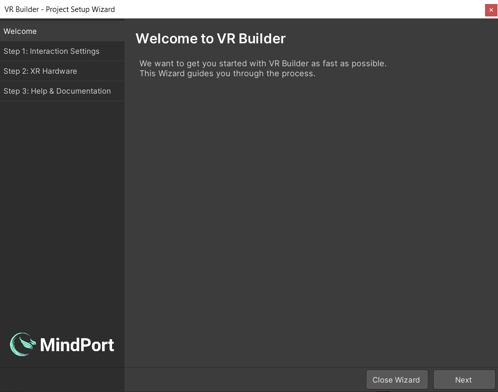
After these notifications the Project Setup Wizard will appear.
Guide Through the Project Setup Wizard
The Setup Wizard helps to get new or existing Unity scenes set up and ready to be used with VR Builder.
Welcome
In the following we will guide you through the different tabs of the VR Builder Setup Wizard.
Click Next to proceed to the interaction settings page setup page.
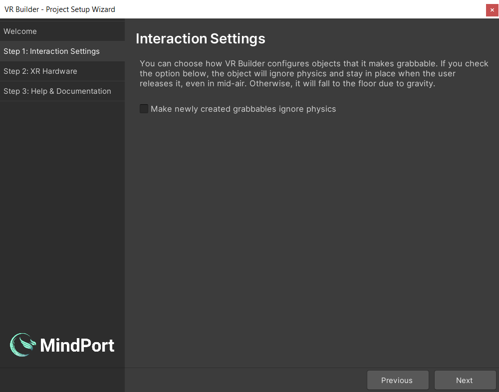
Interaction Settings
Here you can configure some default settings related to VR Builder interactions. Right now, the only available setting will determine whether a newly created grabbable object will use physics or not. You can also change these options at any time in Project Settings > VR Builder > Settings.
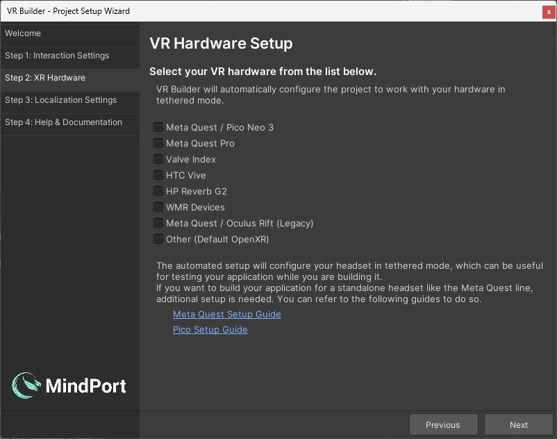
XR Hardware Setup
Then, if it's not configured already, you will be able to configure your project to work with your VR hardware. If your hardware is not listed but supports OpenXR, select Other. You might need to finish the configuration under Project Settings -> XR Plug-in Management. If your device is not supported, please reach out to us in the VR Builder Community. The packages for the selected hardware will be imported after closing the wizard.
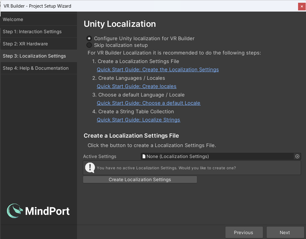
Unity Localization
Finally you must choose whether to set up localization support or skip it for now. VR Builder supports localization through the Unity Localization package. When setting up localization, the wizard will guide you through the manual steps required for a localized project. It provides a useful checklist and some shortcuts to make the task easier. It also has links that redirect to the relevant Unity documentation. If you decide to skip this setup, VR Builder will work in a single language. You can perform localization setup at any time. We encourage you to use Unity Localization, even if you use just one language. With Unity Localization, you will have all your texts in one place inside the Unity Localization Tables, which in turn will give you the possibility to export and refine them and import them back into Unity. Note that as of January 2024, we do not support asset localization tables. See Resources path/Key in the Documentation on how to localize audio files.
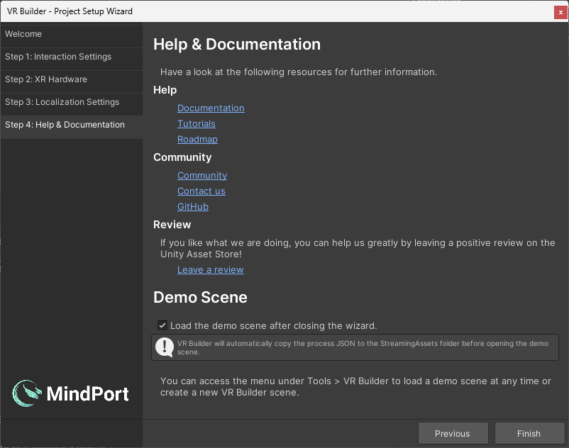
Help & Documentation
This page lists some useful resources to get you started with VR Builder. There is also a checkbox which lets you choose if the demo scene should be loaded after closing the wizard.After clicking Finish, VR Builder is set up! You will need to wait a few seconds for packages to import if you selected a headset from the hardware list. Then, feel free to try out the demo scene or create your own scene by selecting Tools > VR Builder > Scene Setup Wizard….
Note that if you selected the Unity URP template in the beginning, the materials on the avatar hands and demo scene will look solid magenta. That's Unity's way to tell you that the materials are not compatible with the current render pipeline. You can rectify this by selecting all materials (by filtering them in the project window), then click Edit > Rendering > Materials > Convert Selected Built-in Materials to URP. You can of course ignore this step if you don't plan to use the provided hand models or the demo scene.
Quick Start
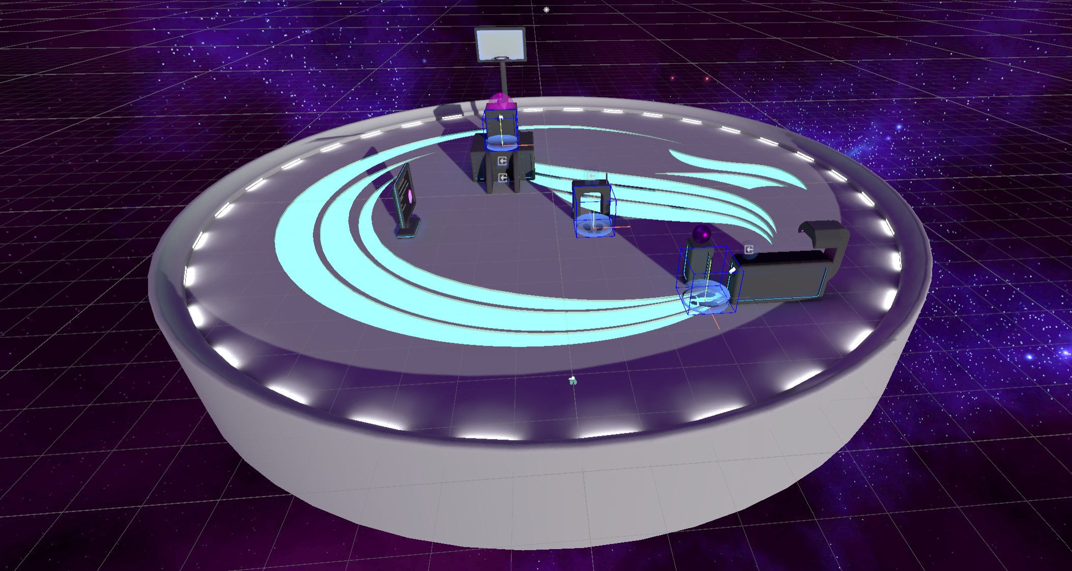
You can get a first impression of VR Builder and its features by accessing the provided demo scene. This sample scene contains a pre-built process that showcases some of the interactions provided in VR Builder.
You can automatically open the demo scene at the end of the setup wizard, or use the shortcut in Tools > VR Builder > Demo Scenes > Core. Note that, while the scene can be found and opened from disk, it is necessary to use one of the above methods at least once in order to automatically copy the process file to the StreamingAssets folder, where VR Builder processes are saved.
Demo Scene Overview
The demo scene showcases how to assemble a process with the building blocks included in VR Builder. More building blocks and features are available as separate add-ons.
These building blocks are either conditions or behaviors. Conditions check if the user or the world is in a certain state, and behaviors modify the world state when activated.
The process in the demo scene is linear, and will guide the user through different steps. To try out the demo scene, ensure audio volume is up, or you won't be able to hear the spoken instructions!
Demo Scene Hierarchy
In the hierarchy there are three game objects in parentheses.
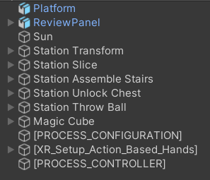
They are automatically added to every VR Builder scene.
[PROCESS_CONFIGURATION]allows to select the process for the current scene from a list of processes saved in the project.[PROCESS_CONTROLLER]defines some parameters for processes in this scene like the spectator input bindings and camera.[XR_Setup_Action_Based_Hands]is the VR rig used by the default XR interaction component. If you are using a different interaction component, for example to use VR Builder in conjunction with Interhaptics or VRIF, you might see a different rig here.
By looking at the other objects in the scene, we can see that some have a Process Scene Object component and possibly some "property" component. A Process Scene Object has a unique object ID that can be accessed by the process. Properties define how the process can interact with the object. For example, a Grabbable Property will let VR Builder recognize if an object is being grabbed. Adding a Grabbable Property to an object will automatically make it a Process Scene Object and add a few components so you can interact with the object in VR.
If these properties are not added manually you will usually be prompted to add them automatically when building the process of your VR application.
Customizing the Rig
Since VR Builder 2.2.0, the rig system has been simplified by removing the [INTERACTION_RIG_LOADER] and dummy rig. The default rig is created directly in the scene and can be edited or replaced like any game object. If you plan to use the same rig in multiple scenes, just create a prefab of it and manually replace the default rig.
The only requirement every VR Builder rig has, independent of the interaction system, is that it must contain a User Scene Object component. This component identifies the rig as the user, and is usually placed on the root of the rig. It should reference the head and hand transforms, so that VR Builder can access those positions when needed. If left empty, it will attempt to find the head by itself by looking for the camera's transform.
It is also possible to add other Process Scene Objects on the rig in order to use hands, backpacks, toolbelts and so on in behaviors and conditions, depending on the use case.
Process Editor
The process editor lets you design the process of your VR application. You can open the process editor from Tools > VR Builder > Process Editor or Window > VR Builder > Process Editor. The process editor for the demo scene should look like this.
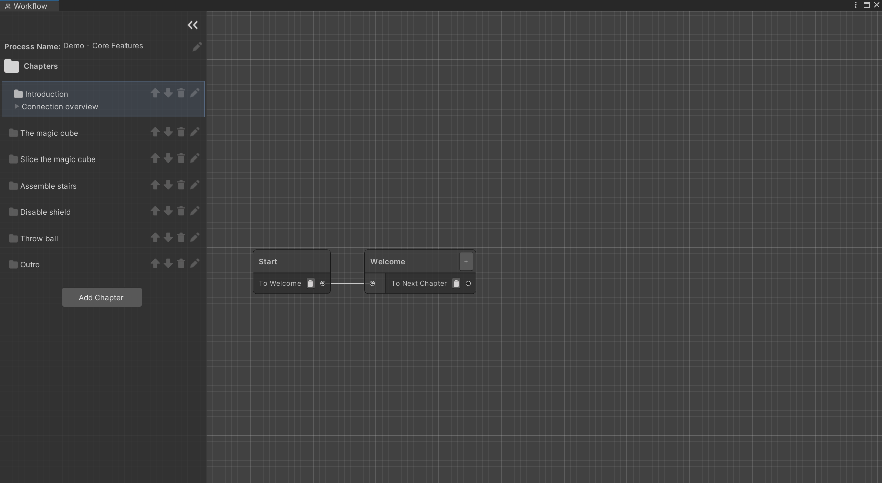
Chapters view
On the left, there is a list of chapters. Every chapter is a separate section of the process. They are useful to separate a process in its logical steps and avoid too much clutter in a single graph.
You can click on the different chapters to visualize the corresponding graphs.
Next to the chapter name, there are icons that allow you to move the chapter up and down in the list, rename it or delete it.
Underneath, you can see the Connections breakdown foldout. Expand it to see incoming and outgoing connections for the current chapter. That is, which chapters lead here and to which chapter it is possible to go from this one. The number next to each connection represents the amount of steps that connect to the chapter. When "Next Chapter" or "Previous Chapter" is listed as a connection, it means the connection is implicit: a path ends with an empty transition, which by default ends the current chapter and starts the next one in order.
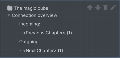
The demo scene is linear, meaning that each chapter will lead directly to the next and the connection overview only contains implicit connections, but it is possible to create more complex processes that don't follow the chapter list linearly.
Graph view
On the right, there is a graphical representation of the current chapter. Every node is called a Step. Every step can include a number of Behaviors which can happen when the node is triggered or before leaving it. In the demo scene, those are mostly text to speech instructions. A step can have as many exit points, called Transitions, as needed. Every transition can list a number of Conditions which, if fulfilled, make the transition valid.
Select the "Welcome" node in the first chapter. This will open the Step Inspector. The window should look like the following.
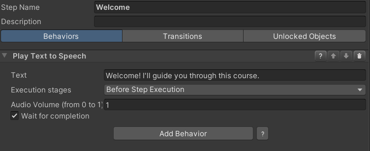
The only behavior is a text to speech instruction that will be triggered when the node is entered. Click on the "Transitions" tab.
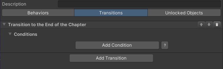
There is a single transition. A step can have multiple transitions, each leading to a different step. In this case, the transition is connected to no other step, so it will end the chapter. The next chapter, "The magic cube", will then start.
Transitions can include conditions. If they do, they will trigger only when the attached conditions are completed. This transition has no conditions, so it will trigger immediately after the current step has ended, without any input from the user.
We encourage you to investigate the other nodes to understand how the demo scene is built.
Step Nodes
You can create a node by right clicking anywhere in the graph and selecting New, then the type of node you want to create. There are four types of node available in VR Builder core:
Step
This is the default step node, the main building block for your process. By default, it is empty. This means that nothing will happen, and the execution will immediately proceed to the next node, if present. You will need to add behaviors and conditions to it in the Step Inspector in order to customize it and build your process logic.
Step Group
This node doesn't let you set conditions and behaviors, but instead can be expanded in a new node graph. It can be populated with other step nodes and act as a "sub-chapter" with some self contained logic. This can help keeping the process tidy.
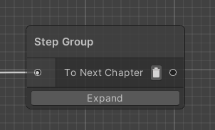
You can access the node's graph by clicking the Expand button or double clicking on the node itself. There are also context menu options for expanding the node or ungrouping it - that is, replacing it in the main graph with the logic it contains.
This node only has one entry and one exit point. This means that after the contained logic has ended executing, the process will always continue executing from the exit transition of the group node.
If you are in a step group graph, it will be indicated on the top left of the process editor.
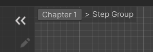
You can click on a parent to return to it. For example, clicking on "Chapter 1" will get you back to the main chapter graph.
You can also create a group by selecting a sequence of nodes, right clicking and selecting Make group. Since the step group node only has one input and one output, this works best when selecting linked nodes only. Edge cases are resolved as follows:
- If there are two or more inbound connections in the group, all will lead to the group's input. The first valid node will be chosen as starting step for the group, while the others will have their connection severed.
- All outgoing connections will be deleted, meaning that the process will continue from the output of the group node after the group has processed. This means that if the selected nodes lead to multiple other nodes, now they will all go through the group's output.
- The step group output will be connected to the previous target of the first valid grouped node. Other external targets in grouped nodes are ignored, which means that when the group ends it will always go to the same following node.
If you encounter one of these edge case, make sure to review your process logic after grouping, as it may have changed.
Parallel Execution
The parallel execution node lets you execute two or more step sequences at the same time. Execution will continue to the next node once all parallel sequences have completed.
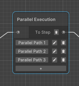
Clicking on a Parallel Path button will open a new graph where the path can be edited. This is very similar to a step group, with the difference that there can be multiple parallel paths and they are all executed at the same time. Like with step groups, it is possible to return to the main process by clicking the root chapter on the top left of the process editor.
The buttons next to a parallel path let you rename or delete it. The "+" button at the bottom lets you add more parallel paths. There is no theoretical limit to the number of paths in a parallel execution node, but performance might suffer.
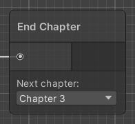
End Chapter
You can use this node as the last node on a sequence. It will end the current chapter and start a new specified chapter, which can be selected from a drop-down list. This is useful to move through the chapters in a non-linear fashion. Note that you are not required to use this node for linear processes, as a chapter will automatically end when an empty transition is reached. In that case, the process will simply proceed to the following chapter.
Note: It is not recommended to use this node inside a step group as it will behave slightly differently (the nodes following the step group will be fast-forwarded before ending the chapter). It is currently not possible to create this node inside a step group.
Process Scene Objects
The Process Scene Object component acts as a bridge between the VR Builder process and a Unity game object. If the process needs to observe or interact with a game object, it does so through this component. This means that every game object referenced in the process is required to have this component. If a more detailed interaction is needed, property components can be added to provide VR Builder more control on the object. For example, adding a Grabbable Property component will make the object grabbable, and VR Builder will be able to check if the object has been grabbed.
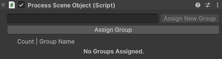
The Process Scene Object generates a hidden object ID which identifies the object internally in the VR Builder process.
In addition, it is possible to associate an arbitrary number of groups to every scene object. Some behaviors and conditions can interact with unspecified objects within a certain group rather than a specific object with a given object ID.
You can select and assign an existing group from the list, or create and directly assign a new group. You can unassign a group from an object by clicking the X button next to it. Groups are stored on a per-project basis and can be created, edited or deleted from Project Settings > VR Builder > Scene Object Groups.
It is possible to edit multiple Process Scene Objects at the same time to add or remove groups in bulk. When multiple objects are selected, all groups on all objects are listed.
If a group is present only on some of the selected objects, it will be displayed in italics. A default text style means that the group is present on all selected objects.
Locomotion
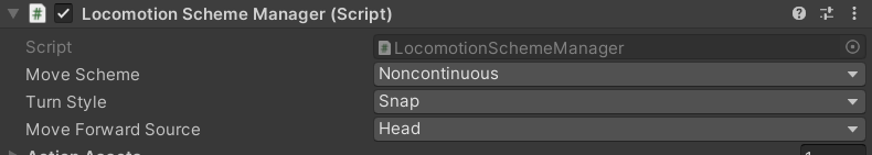
The default rig supports locomotion by teleportation or continuous movement. By default, the rig is set to work with teleportation only, you can change this settings on the Locomotion Scheme Manager component on the XR Rig child object.
Continuous Movement
Continuous movement is controlled by default with the thumbsticks. Left to move around, right to turn on the spot. In general, we don't recommend this locomotion solution as it can cause motion sickness in inexperienced users, however it can still be useful for specific use cases, precision adjustments or testing.
Teleportation
Teleportation requires the user to hold the trigger, then release while pointing at a teleportable surface or anchor. Teleportation requires a little more setup to work properly, but most of it is handled automatically by VR Builder.
It is recommended for teleportation to work on different layer than normal interactions. By default, VR Builder uses the XR Teleport raycast layer for raycasts from the teleportation controllers, and the XR Teleport XRI interaction layer for teleportation interaction.
This means that interactors and interactables need to be configured with these layers in order to work. When a new scene is created, the teleport interactors on the default rig are automatically configured to raycast and interact on these layers.
Likewise, when creating a teleportation anchor or area, you should use the Teleportation Anchor (VR Builder) or Teleportation Area (VR Builder) components instead of the XRI versions. These include a button in the inspector which automatically configures them to settings compatible with the VR Builder rig, including layer settings.
The teleportation anchor in particular also include two more options: you can create a default anchor complete with graphics and collider, and you can enable proximity detection (see Teleport condition).
Given this, teleportation should be easy to setup and just work out of the box. In case something does not, for example when editing an old scene or after changing the position of the XR Teleport layer, it is possible to reset the layers on the rig and all anchors and areas in the scene. To do so, select Tools > VR Builder > Developer > Configure Teleportation Layers. Note that this will overwrite your existing layer masks and select the XR Teleport layer on all of them.
Behaviors
Behaviors are used to make something happen in the process. Behaviors can be as simple as giving instructions and hints, making new objects visible, or animating an object in the scene. What they have in common is that something happens without requiring an intervention by the user. This section lists the behaviors included in VR Builder.
Guidance
Play Audio File
Description
The Play Audio File behavior plays an audio clip loaded from the Resources folder in your project’s asset folder. VR Builder supports all audio file formats supported by Unity, which are:
- aif
- wav
- mp3
- ogg
Configuration
Resources path/Key
Insert the relative file path from the Resources folder. Please note that you have to omit the file extension, as shown in the example. You can find more information about this on https://docs.unity3d.com/ScriptReference/Resources.Load.html.
If localization is enabled, this should instead be a key in the localization table associated with the process, which contains the localized resources path.
Example without localization
File to be played:Assets/.../Resources/Sounds/click-sound.ogg
Text/Key:Sounds/click-soundExample with localization
File to be played:Assets/.../Resources/Sounds/click-sound.ogg
Text/Key:click-sound-key
Localization table translation:Sounds/click-soundVolume
The volume at which the audio should be played.
Execution stages
By default, steps execute behaviors in the beginning, in their activation stage. This can be changed with the
Execution stagesdropdown menu:Before Step Execution: The step invokes the behavior during its activation.After Step Execution: Once a transition to another step has been selected and the current step starts deactivating, the behavior is invoked.Before and After Step Execution: Execution at activation and deactivation of a step.
Wait for completion
By default, the step waits for the audio file to finish. If you want the step to interrupt the audio in case the step is completed, uncheck this option.
Note: this might lead to an audio file not even being started, in case the step ends immediately.
Play TextToSpeech Audio
Description
The Play TextToSpeech Audio behavior uses a synthesized voice to read text. It supports localized text through Unity's Localization package.
By default, VR Builder works with a single language. In Project Settings > VR Builder > Language you can specify which language will be used by the TTS engine.
VR Builder can also be configured to use the Localization package from Unity to provide localized text. The Project Setup Wizard can guide you through the steps, which are the same as outlined in the official documentation.
VR Builder will automatically switch to localized mode when a Localization Settings object has been created.
Configuration
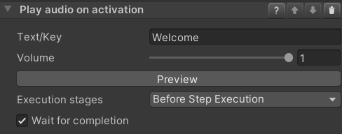
Text/Key
If the project is not configured for localization, this field can be used to enter the text that will be spoken in the language configured in the Project Settings.
If localization is configured, meaning that a Localization Settings object has been created, you need instead to enter the key to look for in the localization table associated with the process.
Volume
The volume at which the audio should be played.
Execution stages
By default, steps execute behaviors in the beginning, in their activation stage. This can be changed with the
Execution stagesdropdown menu:Before Step Execution: The step invokes the behavior during its activation.After Step Execution: Once a transition to another step has been selected and the current step starts deactivating, the behavior is invoked.Before and After Step Execution: Execution at activation and deactivation of a step.
Wait for completion
By default, the step waits for the audio file to finish. If you want the step to interrupt the audio in case the trainee completes the conditions, uncheck this option.
Note: this might lead to an audio file not even being started, in case the step ends immediately.
Highlight Object
Description
The Highlight Object behavior visually highlights the selected object until the end of a step.
For additional highting features you can replace the Default Highlighter with a Interactable Highlighter Script. Select the highlighted Object in the Unity Hierarchy. In the Unity Inspector replace the DefaultHighlighter with a Interactable Highlighter Script.

You can define the Color and Material for On Touch Highlight, On Grab Highlight, and On Use Highlight. The object will show the highlight color configured in the Highlight behavior by default. As soon as the object is touched it will change to the color configured in On Touch Highlight. The same happens when the object is grabbed or used. It will display the configured color in ‘On Grab Highlight’ or ‘On Use Highlight’.
Configuration
Color
Color in which the target object will be highlighted. Colors are defined in the RGBA or HSV color channel. By configuring the alpha (A) value, highlights can be translucent.
Object
The
Process Scene Objectwhich should be highlighted.
Spawn Confetti
Description
The Spawn Confetti behavior causes confetti to fall above the selected Object. It can be useful as visual feedback or celebration for completing a task successfully.
Configuration
Spawn Above User
If checked, the spawn position will be above the user rather than on the specified
Process Scene Object.Position Provider
Specifies where the confetti should spawn if not set to spawn above the user.
Confetti Machine Path
Path to the confetti machine prefab, relative to a
Resourcesfolder. Use the default one or point to your custom confetti machine.Area Radius
Radius around the position provider in which confetti will be spawned.
Duration
Duration of the visual effect in seconds.
Execution stages
By default, steps execute behaviors in the beginning, in their activation stage. This can be changed with the
Execution stagesdropdown menu:Before Step Execution: The step invokes the behavior during its activation.After Step Execution: Once a transition to another step has been selected and the current step starts deactivating, the behavior is invoked.Before and After Step Execution: Execution at activation and deactivation of a step.
Utility
Behavior Sequence
Description
The Behavior Sequence contains a list of child behaviors which will be activated one after another. A child behavior in the list will not be activated until the previous child behavior has finished its life cycle.
Configuration
Repeat
If checked, the behavior sequence restarts from the top of the child behavior list as soon as the life cycle of the last child behavior in the list has finished.
Child behaviors
List of all queued behaviors. Add behaviors to the list using the "Add Behavior" button.
Wait for completion
If checked, the behavior sequence will finish the life cycle of each child behavior in the list before it transitions to another step. Even when the "Repeat" option is enabled, the execution will transition to the next step after the child behavior list has been completed. Uncheck this option if you want to interrupt the sequence as soon as all conditions of a transition are fulfilled.
Example
Play an audio file after a set time, for example to give the user some delayed hints.
This is a sequence combining a Delay and a Play Audio File behavior. Refer to the documentation for the Delay behavior and the Play Audio File behavior.
Delay
Description
The Delay behavior completes after the specified amount of time. This step will wait for the duration configured in Delay (in seconds), even when the user fulfills the required conditions to transition to the next step.
Configuration
Delay (in seconds)
Configure the behavior’s delay duration in seconds.
Example
Delay (in seconds) = 1.3
Set Parent
Description
The Set Parent behavior parents an Object to another one in the Unity hierarchy.
Configuration
Target
The
Process Scene Objectto be parented.Parent
The new parent for the target object. Note this can be null, in which case the object will be unparented.
Snap to parent transform
If checked, the target object will snap to the same position and rotation as the parent object.
Environment
Disable Objects
Description
The Disable Objects behavior makes the selected Objects invisible and non-interactive until they are specifically set back to "enabled" in a future step. Put into Unity terms, it deactivates the selected Game Objects.
Configuration
Objects
The
Process Scene Objectsto be disabled.
Enable Objects
Description
The Enable Objects behavior makes the selected Objects visible and interactive until it is specifically set back to "disabled" in a future step.
Put into Unity terms, it activates the selected Game Objects.
Configuration
Object
The
Process Scene Objectsto be enabled.
Disable Components
Description
The Disable Components behavior disables all components of the specified type on the given Process Scene Objects.
Configuration
Object
The
Process Scene Objectsthe component is on.Component type
A drop-down list allowing to select the component type that will be disabled.
Enable at end of step
If checked, the components will be enabled again at the end of the step.
Enable Components
Description
The Enable Components behavior enables all components of a specified type on the given Process Scene Objects.
Configuration
Object
The
Process Scene Objectsthe component is on.Component type
A drop-down list allowing to select the component type that will be enabled.
Disable at end of step
If checked, the components will be disabled again at the end of the step.
Unsnap Object
Description
The Unsnap Object behavior unsnaps a snapped object from a snap zone. This can be useful in case the object needs to be further manipulated by the process.
Configuration
Either the object or the snap zone can be left null. This will result in either the object unsnapping from any snap zone it is in, or in the unsnapping of whatever object is snapped to the specified snap zone.
If both are specified, the unsnap will occur only if the specified object is snapped to the specified snap zone.
Object to unsnap
The
Process Scene Objectto unsnap.Snap zone to unsnap
The
Snap Zonefrom which the object will be unsnapped.
Animation
Move Object
Description
The Move Object behavior animates the Object to move and rotate (no scaling) to the position and rotation of the Final Position Provider in the time specified in the Duration (in seconds) parameter.
Note: If Object was affected by gravity before, it will continue to be affected after this behavior.
Configuration
Object
The
Process Scene Objectto be moved and rotated (no scaling).Final position provider
The
Process Scene Objectused as the position provider object. It should be placed at the destination position and rotation.Animation duration (in seconds)
Time in seconds the animation takes to move and rotate
Objectto theFinal position provider.Example
Duration (in seconds) = 1.3
Conditions
Conditions are used to determine which transition is used to exit a step. Transitions are evaluated top to bottom, and the first valid one will be selected. To be valid means to have only fulfilled conditions or no conditions at all. A condition usually requires the user's intervention, for example grabbing an object. However this is not always the case: conditions like the timeout condition will trigger regardless of the user’s activity. There may also be cases in which other factors in the environment determine if a condition is fulfilled. Conditions need to be active in order to be fulfilled. As soon as a step is active, all containing Conditions are active as well. This section lists the conditions included in VR Builder.
Environment
Move Objects in Collider
Description
The Move Objects in Collider condition is fulfilled when the Objects are within the specified Collider for the required amount of time (Required seconds inside) while this condition is active.
Configuration
Object
The
Process Scene Objectsto move. If the objects need to be grabbed, they need to have theGrabbable Propertyand a collider component configured. The collider defines the area where the user can grab an object.Collider
The
Process Scene Objectwith the destination collider. Make sure that a collider is present and that the optionIs Triggeris enabled.Required seconds inside
Set the time in seconds that the
Objectsshould stay inside theCollider.
Object Nearby
Description
The Object Nearby condition is fulfilled when the Object is within the specified Range of a Reference object.
Configuration
Object
The
Process Scene Objectthat should be in the radius of theReference Object.Reference Object
The
Process Scene Objectfrom which you want to measure the distance.Range
In this field, you can set the maximum distance between the Object and the Reference object required to fulfill this condition.
Required seconds inside
In this field, you can set the time in seconds the
Objectshould stay within the radiusRangeof theReference Object.
Interaction
Grab Objects
Description
The Grab Object condition is fulfilled when the user grabs any of the Objects.
The condition is also fulfilled if the user already grabbed any of Objects before the step was activated, that is, if the user is already holding the specified object.
Configuration
Objects
The
Process Scene Objectsto grab. The objects needs to have theGrabbable Propertyand a collider component configured. The collider defines the area where the user can grab an object.
Release Objects
Description
The Release Objects condition is fulfilled when all of the Objects are released by the user's controller. If the user is not already holding any of the specified objects in hand while this condition is active, it is fulfilled immediately.
Configuration
Objects
The
Process Scene Objectsto release. The objects need to have theGrabbable Propertyand a collider component configured.
Snap Objects
Description
The Snap Object condition is fulfilled when any of the Objects is released into the Zone to snap into, which means the collider of any of the Objects and collider of the Zone overlap. Adapt the collider size of the snap zone to increase or decrease the area where the user can release an Object. Increasing the collider size of the snap zone decreases the required snap precision and simplifies the user's interaction in VR.
After the user releases an Object, this is moved to the snap zone's SnapPoint. To adjust this position, change the position of the SnapPoint child object of the Zone to snap into object.
Snap Zone Generator
For any snappable object you can generate a snap zone that can snap this object and can be used as a
Zone to snap into. To do so, navigate to theSnappable Propertyin Unity's Inspector. You will see two buttons. Clicking on the buttonCreate Snap Zone for this object, you will create a snap zone that only accepts this exact object. Clicking onCreate Snap Zone for objects in the same groupswill instead create a snap zone that accepts every object that shares at least a group with the current object. Note that the current object will still determine the shape of the snap zone's ghost object.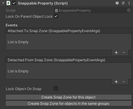
If you want a specific snap zone behavior, like for example accepting only one group of the source object instead of all of them, you'll have to manually change that. Select the snap zone and find the
Has Guid Validationcomponent. If you manually created your snap zone, you might have to add this component manually as well. Add to the list the objects you want to be valid for this snap zone. You can reference single objects by object ID, or entire categories of objects via groups.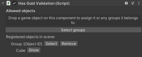
Manual Snap Zone Creation
Instead of the automatic generation as described above, you can do those steps also manually. Please refer to available documentation on the
XRSocketInteractorfrom Unity or related sources. You can also make changes to the automatically created snap zone to adapt it to your needs. Please note that these changes might impact the process logic.Feed Forward for Snap Zones
Snap zones are restricted to which objects can be snapped. This means every object can be valid (i.e. it can be snapped to this zone) or invalid (it can not be snapped to this zone) for a snap zone. This is achieved with validation components on the snap zone, for example the
Has Guid Validationcomponent. You can use this component to configure which specific objects or groups are accepted by the snap zone. In case you are moving a valid object into a zone, the snap zone color changes to ‘Validation Color’ (green), providing the user in VR with positive feedback. In case you are moving an invalid object into a zone, the snap zone color changes to ‘Invalid Color’ (red), giving the user the feedback that this is the wrong object for this zone. You can modify the colors and materials to be used in the Snap Zones parameters and settings.Snap Zone Parameters and Settings
To change the highlight color or validation hover material of a dedicated snap zone, navigate to the snap zone object in the Unity Inspector. You will find the Snap Zone Parameters and Settings in the script
Snap Zone.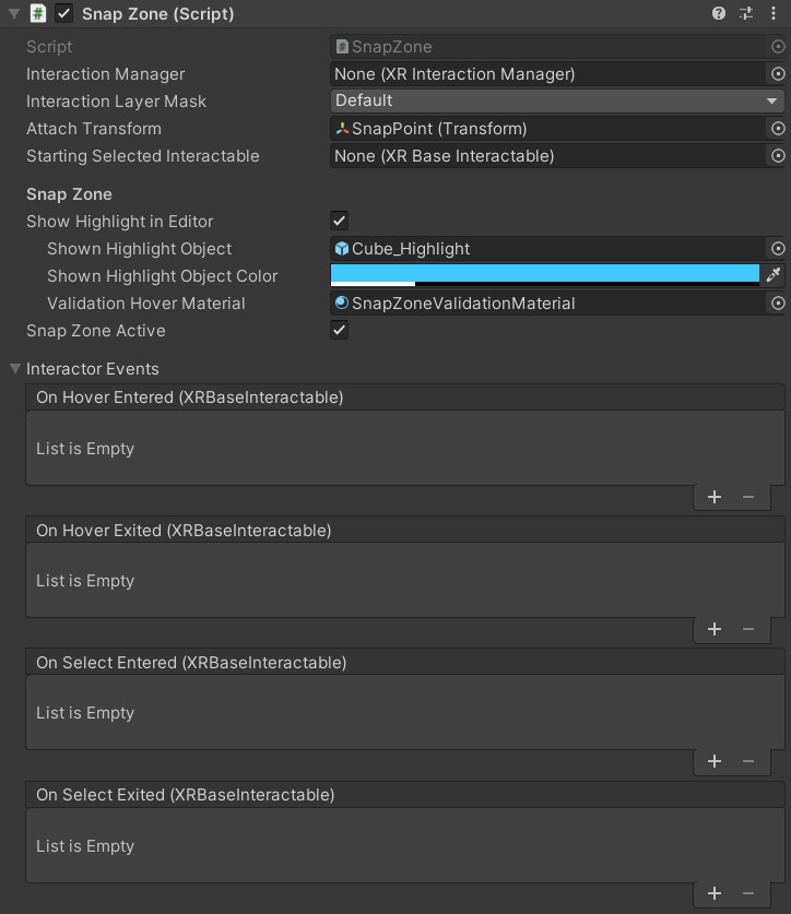
To change the colors and materials of all snap zones in the scene, select them in the VR Builder snap zone settings and press 'Apply settings in current scene'.
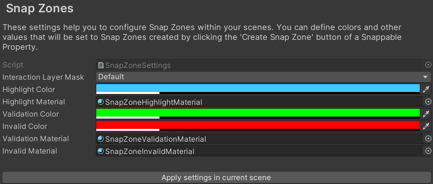
The snap zone settings can be found in the project settings in tab
VR Builder > Settings > Snap Zones.
Configuration
Objects
The
Process Scene Objectsto place (snap). The objects needs to have theSnappable Propertyand a collider component configured.Zone to snap into
This field contains the
Process Scene Objectwhere any of theObjectsare required to be snapped. Make sure the object has a collider component with theIs Triggerproperty enabled.
Touch Objects
Description
The Touch Object condition is fulfilled when any of the Objects is touched by the user's controller. If a user is already touching the any of the objects while this condition is active, this condition is fulfilled immediately.
Configuration
Object
The
Process Scene Objectsto be touched. The objects needs to have theTouchable Propertyand a collider component configured.
Use Objects
Description
The Use Objects condition is fulfilled when any of the Objects are used by pressing the Use button of the controller while being touched or grabbed.
Configuration
Objects
The
Process Scene Objectsof which one is required to be used. TheObjectsneed to have theUsable Propertyand a collider component configured.
Utility
Timeout
Description
The Timeout condition is fulfilled when the time specified in Wait (in seconds) has elapsed. This can make sense as a "fallback" condition. For example, if the user does not complete condition X in the allotted amount of time, the timeout condition will trigger leading to a different step with different consequences.
Configuration
Wait (in seconds)
Set the time in seconds that should elapse before this condition is fulfilled.
Locomotion
Teleport
Description
The Teleport condition is fulfilled when the user teleports to any of the referenced Teleportation Points. Previous teleportation actions made into a Teleportation Point are not considered.
If an anchor used as Teleportation Point has proximity detection enabled, the condition will be fulfilled not only if the user teleports to it, but also if they move close to it with continuous movement or by walking in the room. You can activate proximity detection when you need the user to be in a specific location, regardless of whether they teleport or arrive there by other locomotion types.
The provided Teleportation Property is based on the Unity XR Interaction Toolkit's Teleportation Anchor. For further reference, please check out the XR Interaction Toolkit documentation.
Configuring a Teleportation Point
The
Teleportation Propertycan be set as a Default Teleportation Anchor by clicking on theSet Default Teleportation Anchorbutton. You can find it when selecting theTeleportation Pointand viewing it in the Unity Inspector.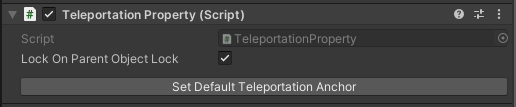
This will configure the attached
Teleportation Anchor. It will provide a visual element in the Unity Editor that helps placing theTeleportation Pointin the scene. This visual element will also be shown in the virtual world during training execution to guide the user.
Configuration
Teleportation Points
The
Teleportation Propertiesof which one, the user should teleport to.
Online Documentation
We offer a constantly expanding list of guides and tutorials on our website. We encourage you to check them out to improve your VR Builder skills.
If this is your first time with VR Builder, you should start from the Process Editor and Step Inspector tutorials, which explain the basics of working with VR Builder.
In addition,you might also want to check out the guides on how to build standalone VR Builder apps on the Oculus Quest or Pico Neo 3.
You can also check out some guides on the more advanced interactions, like the series on snap zones.
Lastly, there are some step-by-step tutorials explaining how to work with our latest paid add-ons. Even if you don't intend to buy the relevant content, they can provide a good overview on how to build a functional process with VR Builder from scratch.
Acknowledgements
VR Builder is based on the open source edition of the Innoactive Creator. While Innoactive helps enterprises to scale VR training, we adopted this tool to provide value for smaller content creators looking to streamline their VR development processes.
Like Innoactive, we believe in the value of open source and will continue to support this approach together with them and the open source community. This means you are welcome to contribute to the VR Builder GitHub repositories.
Contact and Support
Join our official Discord server for quick support from the developer and fellow users. Suggest and vote on new ideas to influence the future of the VR Builder.
Make sure to review VR Builder on the Unity Asset Store if you like it. This will help us sustain the development of VR Builder.
If you have any issues, please contact contact@mindport.co. We'd love to get your feedback, both positive and constructive. By sharing your feedback you help us improve - thank you in advance! Let's build something extraordinary!
You can also visit our website at mindport.co.